| Overview |
| Using Fluid Samples |
| Reducing Evaporation |
| Preventing Slippage |
| Particulate Samples |
| Temperature Compensation |
| Normal Force Control |
This topic describes some sources of error that may arise when making rheological measurements. It is important to remember that all samples are different, and that the solutions suggested here are for guidance only and may not be suitable for your material. If you are running an unknown sample, or one that differs substantially from those that you are familiar with, it usually helps to try various ways of sample filling, loading, and so on. The key to obtaining good rheological data is to take care at every step: sampling, loading, filling, and running.
Avoid shearing the sample excessively during loading. Thixotropic samples may take a considerable time to recover from shearing, and in some cases are irreversibly shear thinning; their original properties will never be recovered. To prevent excessive shearing, the geometry gap can be closed at a fixed rate profile, or the gap closure can be programmed so that a particular normal force is not exceeded.
The gap closure rate should be as slow as reasonably possible. Rapid closure can result in the sample experiencing surprisingly high shear rates. It is usually best to use normal force control during closure; the force used will depend on the sample. Typical force would be about 1 N for a dispersion and about 5 to 10 N for a polymer melt.
It is important that the sample is filled correctly. The measuring system factors given in the AR Series Getting Started Guide apply only to the correctly filled sample. Either overfilling or underfilling will result in the wrong values for the sample material properties being returned by TRIOS Software.
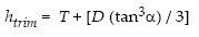
The correct gap is at the truncation distance, T, which is inscribed on the shaft of each geometry. For the sample filling, imagine a sphere centered on the virtual tip of the cone, with a radius equal to the slant length of the geometry. The sample should be the segment of this sphere contained between the cone and the plate. This filling can be difficult to achieve in practice, but there are several ways in which a good approximation can be achieved:
where D is the geometry diameter and a is the cone angle.
The correct fill is with the sample in the form of a disc, with its edge flush with the rim of the geometry. This is usually easier to achieve than the cone and plate fill, and there are several ways of achieving an almost exact filling. Methods 1 and 3 described above for the cone and plate can also be used for the parallel plate. If the sample is underfilled slightly using the parallel plate, unlike with cone and plate it may not be necessary to begin the filling again. The gap can be reduced until the filling is correct.
In addition to the methods used for the cone and plate, some samples can be preformed into a disc of the correct dimensions.
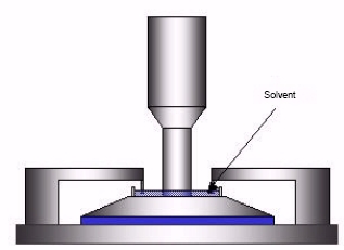
Samples containing volatile solvents can if the solvent evaporates. Use the solvent trap cover to reduce the rate of evaporation. The moat on the top of the geometry should be filled with the appropriate solvent, and the two halves of the cover placed such that the rim is partially immersed in the solvent. Ensure that no part of the cover is in contact with the geometry. If the solvent trap cover is used with the serrated cover plate, the spacer is required to ensure that the cover is set at the correct height.
Slippage can take two forms. In one case, the lack of adhesion between the sample and the surfaces of the measuring system produces a form of plug flow. In another type of slippage, a thin layer of depleted samples occurs at the measuring system wall, resulting in a low apparent viscosity. Both forms of slippage can usually be overcome by texturing the surfaces of the measuring system. This is normally only done for the parallel plate stainless steel measuring system.
When using the parallel plate measuring system, keep in mind the following guidelines to prevent slippage:
When using the concentric cylinder measuring system, use a vane rotor and grooved cup to prevent slippage.
The cone and plate system is not recommended for samples containing any particles with diameters greater than ten percent of the cone truncation. Remember that the particle sizes quoted by suppliers are often average values; there may be some much larger particles present. If in doubt, use a parallel plate, but again observe the ten percent rule: the gap should be at least ten times the diameter of the largest particle.
A change in temperature will produce a change in the dimensions of the components of the instrument, including the geometry. The only significant effect of this will be to change the measuring system gap. This can be allowed for if the thermal expansion coefficient is known. A correction can be invoked when performing an experiment under non-isothermal conditions, such as a temperature ramp or sweep.
To minimize the effect of thermal expansion, the geometry gap should be zeroed at the working temperature for isothermal experiments, or at a temperature in the middle of the range for non-isothermal experiments. The cone and plate measuring system is not recommended for non-isothermal experiments.
To allow for the change in sample dimensions during non-isothermal experiments, constant normal force, rather than constant gap, conditions can be used. It is usually best to use a zero or slightly compressive (positive) force.
