DHR/AR Rheometer Service Utilities
Bearing Test
This test checks the raw performance of the bearing. You may be asked to run this test by a TA Instruments representative to help in fault diagnosis. Any geometry and draw rod should be removed prior to starting the test. A forward and reverse plot of torque vs. displacement is created which can be saved as a TRIOS .tri file and emailed if required.
An additional check of residual torque following mapping can also be carried out as part of the bearing test, and the result will be included in the data file.
Encoder Linearization
This calibration should only be required following a service task in which the encoder was removed, and will be generally performed by the service representative. If you are requested to perform this calibration, follow the on screen instructions and ensure that the instrument bench is free from vibration and the instrument can be completely undisturbed for the duration of the calibration – typically about an hour.
Back to top
Program Smart Swap
Use the following steps to reprogram the serial number.
- Fit geometry.
- Click Program.
- The serial number will be read from the geometry and you will be asked to reconfirm that you want to reprogram the geometry. A value of 1000 means that it has not been previously programmed.
- Enter the serial number of the geometry (located on the geometry shaft and/or storage box).
- NOTE: The adapter and UHP shafts are special cases; these cannot be uniquely identified.
- The geometry begins programming. Upon completion, the dialog box closes.
- NOTE: If the serial number is not already associated with a geometry file in the controller database when the geometry is read, the link must be established through the Geometry Wizard.
Back to top
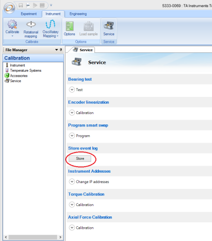
Store Event Log
An instrument event log is stored every time TRIOS is closed. The time and dated text files are located in C:\ProgramData\TA Instruments\TRIOS\Discovery HR-X\Logs, where X is 1, 2, or 3 depending on the version of your DHR. You may be asked to send event logs by a TA Instruments representative to help in fault diagnosis. The Store button, which can be accessed from the Service toolbar on the Instrument tab, allows saving of the log without closing TRIOS. In the case of an instrument error always store the event log, or close TRIOS so that it is stored automatically, before turning the instrument off.
Instrument Addresses
Generally the choice of instrument address type (DHCP or fixed) will be made using the instrument display and front panel. If the default fixed IP address is not suitable for your setup then it can be changed here.
A password can also be setup to limit connectivity to your instrument. This is most useful when there are a number of instruments displayed in TAIE and you want to avoid mistaken connections.
- NOTE: If you forget the password, it can be cleared by following instructions on the instrument display. Use the cycle display button on the keypad to navigate to the correct screen.
Back to top
Axial Force Calibration
The 546099.901 DHR Axial Force Calibration Kit consists of a Weight Hook Adapter, 1,000g Calibration Weight, and Certificate.
- Warning: Do not run this calibration unless you have the correct calibration kit. Any attempt to run this calibration without the correct kit or not following the instructions may make your rheometer unusable, and will require a service visit to rectify.
- Important: The calibration weight is certified and should be handled with care and kept clean.
Calibrating the Axial Force
- Follow the wizard instructions.
- Enter the certified mass in the field provided.
- Attach the Weight Hook Adapter in the same way you would attach a geometry and press Calibrate.
- Hook the calibrated weight on to the adapter and press Continue.
- Axial force calibration factors outside of the range 0.8 – 1.2 are ignored and the existing calibration will not be changed. Contact your TA Instruments Service Representative if you at getting numbers outside of this range.
Back to top
Torque Calibration
The 581024.901 Torque calibration kit consists of a test fixture and certificate.
It is recommended that this calibration be run as a check and a full calibration carried out only if the check error is greater than 0.5%.
- WARNING: Do not run this calibration unless you have the correct torque calibration kit. Any attempt to run this calibration without the correct kit or not following the instructions below may make your rheometer unusable, and will require a service visit to rectify.
- Important: The test fixture has been expensively calibrated. Dropping or otherwise damaging the fixture will render it useless. Keep it clean.
Checking the Torque Calibration
This procedure will guide you through torque calibration of an AR or DHR instrument, utilizing the Moment of Inertia (MOI) test fixture.
- Enter the certified Moment of Inertia from the test certificate in the field provided.
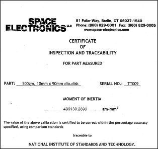
Below is a copy of the certificate that will come with each individual disk. The Moment of Inertia is listed in gm-mm2. You need to enter it in units of µNms2. For example, the certificate below lists the Moment of Inertia as 499130.2898 gm-mm2. Enter the fixture inertia as 499.13 µNms2. To calculate the fixed inertia, multiply the number on the certificate by 0.001.
- Fit the draw rod (but not the fixture). Make sure there is no rotation of the shaft, and then press Check.
- The message "Measuring Rheometer inertia" displays.
- When complete, you will be prompted to attach the test fixture (MOI disk). Attach this in the same way you would attach a geometry. One side will attach to AR1500ex/AR2000ex and the other side will attach to DHR/AR.
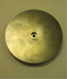
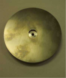
| AR1500ex/AR2000ex side |
DHR/AR-G2 side |
- Make sure there is no rotation and then press Continue.
- NOTE: It is possible when attaching to a DHR/AR-G2 to induce a magnetic bearing instability error. If this happens you will need to cancel the calibration and start again.
- During the calibration the message will change from "Measuring fixture inertia," to "Check completed."
- If the calibration error is less than ±0.5% there is no need to perform the calibration. Press Close and remove the test fixture.
Back to top
Calibrating the Torque
- Enter the certified Moment of Inertia from the test certificate in the field provided.
Below is a copy of the certificate that will come with each individual disk. The Moment of Inertia is listed in gm-mm2. You need to enter it in units of µNms2. For example, the certificate below lists the Moment of Inertia as 499130.2898 gm-mm2. Enter the fixture inertia as 499.13 µNms2. To calculate the fixed inertia, multiply the number on the certificate by 0.001.
- Fit the draw rod (but not the fixture). Make sure there is no rotation of the shaft, and then press Calibrate.
- The message "Measuring Rheometer inertia" displays.
- When complete, you will be prompted to attach the test fixture (MOI disk). Attach this in the same way you would attach a geometry. One side will attach to AR1500ex/AR2000ex and the other side will attach to DHR/AR.
| AR1500ex/AR2000ex side |
DHR/AR-G2 side |
- Make sure there is no rotation and then press Continue.
- NOTE: It is possible when attaching to a DHR/AR-G2 to induce a magnetic bearing instability error. If this happens you will need to cancel the calibration and start again.
- During the calibration the message will change from "Measuring fixture inertia," to "Checking calibration," to "Calibration completed."
- The calibration error should be less than ±0.1%. Press Close and remove the test fixture.
Back to top
