SER Geometry for the DHR/AR Rheometer
Overview
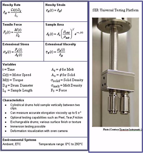
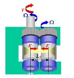
The SER2 is a universal testing platform that performs extensional rheology measurements and a broad range of physical material tests. The SER2 design is based on the Meissner concept, which elongates the sample within a confined space by expelling the sample with rotary clamps. Instead of the rotary clamps, two cylinders are used to wind up the sample. The ends of the test specimen are secured to the surfaces of the two windup drums, such that for a constant drum rotation speed (Wt), a constant Hencky strain rate is achieved. (See the figure below). As the specimen is stretched across the drum surfaces, it offers a resistant force F, on the windup drums that translates into a torque M(t), about the primary axis of rotation. For a given extensional rate, the measured torque signal is directly related to the extensional viscosity of the specimen being stretched in the isolated 'stretch zone' of length Ls, defined by the tangent plane between the two drums.
In addition to extensional measurements on polymer melts, the SER2 is capable of performing a range of physical property measurements such as tensile, peel, tear, and friction measurements on miniature hard and soft solid samples.
Back to top
Description
The schematics of the Universal Testing Platform (SER2) are given in the figure below. The SER is connected via the SER base adapter to the SER bracket, mounted to the test head of the AR Rheometer. The SER drive shaft connects the motor spindle to the SER, aligning the motor spindle with the primary rotating drum. The second drum is driven by the first, at the same rotation speed in opposite direction by the spur gears mounted to the drive shaft of the two drums. The lateral offset of the center axis of the two drums is 12.7 mm. The diameter of the drums is 10.3 mm and the clearance between the drums is 2.4 mm. The drums can be removed from the drive shaft easily and exchanged. The SER2 is designed to fit into the standard AR ETC.
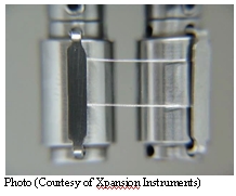
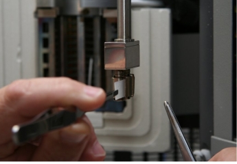
The figure below shows the SER2 option installed on the AR2000ex Rheometer. Since the cylindrical drums are
mounted vertically, the sample is also loaded vertically onto the drums and attached with two tiny clips.
Sample Support
On the SER2, the samples are mounted vertically and the sample length LS is reduced to 12.7 mm. Materials with a shear viscosity above 1000 Pa.s do not significantly sag under the effect of gravity as a result of the high stiffness due to the vertical arrangement. Because of the small sample size and the fast heating rate of the AR ETC, the waiting time after loading the sample can be reduced to less than a few minutes, thus preventing creep in the sample. The gravitational force does not contribute to the force measurements because of the horizontal alignment of the sample.
Back to top
Preparing Samples
Sample preparation is an important criterion to obtain good data up to the maximum achievable Hencky strain. Sample non-uniformity and necking decrease the measured force, which results in a viscosity decrease. Sample homogeneity is a fundamental requirement for good elongation measurements up to Hencky rates of 4 and more. The goal of sample preparation is to make a homogeneous and stress free sample of the correct size.
The optimum sample size is recommended as follows:
- Length = 18 mm
- Width = 10 mm
- Thickness = 0.7 mm
The best method to prepare samples is Hot Compression Molding (see the next section). The samples should be molded at a temperature above the test temperature and cooled slowly under pressure to obtain relaxed and stress free homogeneous samples with minimum dimensional variation.
- NOTE: Samples with a high crystallinity content are difficult to mold stress free. Special care must be taken to anneal these samples before loading them into the instrument.
Hot Compression Molding for Test Samples
Molding conditions may vary depending on the melt temperature and relaxation properties of the materials being prepared. A basic method to mold samples for use with the SER2 is described below:
- Preheat the press to approximately 10 to 30°C above the temperature that will be used during the experiment.
- Obtain a stiff upper and lower plate.
- Cover the plate, if desired, with a polyester film or a Teflon®-coated aluminum foil.
- Place a thin gauge molding plate (approximately 50 x 50 mm) on top of the foil.
- Calculate the amount of sample needed, then add 30 percent extra.
- Spread the sample evenly.
- Place the top plate over the sample and place the entire assembly into the press.
- After the mold reaches the desired molding temperature, wait three to five minutes to allow the sample to melt, then press the sample with a load of 5-10 metric tons (10,000 to 20,000 pounds) for a period of 10 to 15 minutes. Provide a sufficient pressing time to allow for stress relaxation at temperature.
- Turn off the heat and allow the sample to cool down with the pressure still applied.
- Remove the molded sample sheet when the temperature has cooled below the glass transition or melting point by pressing the samples out of the mold.
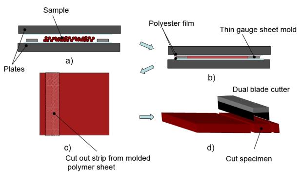
- Use a dual blade cutter to cut strips of 10-12 mm width, preferably from the middle section of the molded polymer sheet. Hard and brittle samples (PS, PMMA, etc.) are best cut with a small jig saw.
- Cut the polymer strips into 18-mm long test specimens.
- NOTE: In some cases (for example, branched or ultra-high molecular weight materials with a very long relaxation time), the melt has to be sheared for homogenization and elimination of the previous structure of the pellets prior to compression molding.
Back to top
Installing the Fixture
Follow the instructions below to install the SER2 Fixture:
- Open the ETC as far as it can go.
- Push the manual stage control button on the bottom panel of the AR test station to raise the stage.
- Remove any current test fixtures.
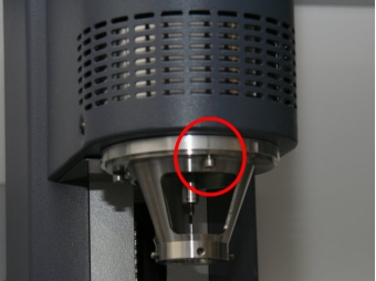
- Mount the SER bracket onto the mounting ring of the AR rheometer head and tighten with the 3 screws (see below).
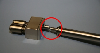
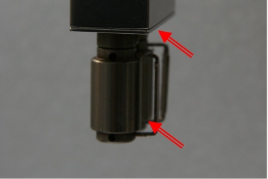
- Connect the SER to the SER drive shaft with the universal joint as shown below and screw the SER base adapter to the SER.
- Insert the SER with the SER drive shaft and base adapter into the SER bracket.
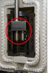
- Orient the SER such that the tangent plane of the two drums faces the ETC camera, if installed (see below). Otherwise, the SER can be oriented to whatever position is found easier for sample loading and cleaning.
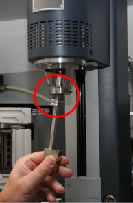
- Tighten the two opposite screws on the SER bracket to lock the SER in position (see below).
- Insert the draw rod from the top and tighten the SER drive shaft on to the rheometer drive shaft. Note that for the AR2000ex, the adapter needs to be used to match the internal diameter of the SER drive shaft with that of the rheometer. The insert is not required for the AR-G2.
- Position the head with the stage control buttons on the bottom panel to center the two drums in the middle of the view field of the camera, as shown below.
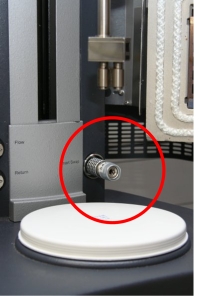
- Insert the SmartSwap™ plug and fit to protect the smart adapter connection from contamination.
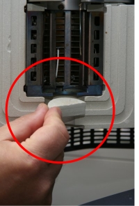
- Insert the two half-disk ceramic pieces to block the ETC opening at the bottom.
- Insert the clips in the drums. Note that the holes for inserting the clips are offset. This is to avoid the clips making contact during rotation.
- Close the ETC and adjust the lighting to optimize the image (only if camera is available).
- Ensure that the drop down ETC thermocouple is in free space and not touching the SER2.
Back to top
Setting Up the Test
For information regarding setting up tests using the SER2 fixture, refer to Setting Up an Extensional Test TRIOS Help topic.
Loading Samples
The quality of your test results depends significantly on the uniformity of the sample and the careful loading of
the sample onto the test fixture. After loading, as the sample heats up to temperature, it is expanding which can
result in the sample adhering to the drum surface between the two drums. This reduces the free sample length
and increases the force when the sample is pulled away from the drum surface at the start up.
- Before running the first test, the SER2 geometry needs to be positioned correctly in the oven.
- Position the drums with the clips facing the camera.
- Select Bearing lock from the Motor section of the Control panel to lock the drums in position (or use the bearing lock
button at the test station bottom panel for the AR-G2. For the AR2000ex, the bearing lock
needs to be enabled from the PC).
- Pull out the clips by 1-2 mm for easy insertion of the sample during loading.
- Close the ETC and wait for temperature equilibrium.
- Check the ETC temperature. When it has reached the desired testing temperature, open the doors carefully.
- Thread the sample (prepared as directed previously in this section) from the front to the rear through the two
opened sample clips. Align the sample with the rear clip.
- Push in the rear clip just enough to touch the sample. Do not press to tightly and do not compress the sample.
- Release the sample and push in the front clip using the same technique. Do not compress the sample. Remove excess sample with the tweezers. The molten sample can be cut easily with the tweezers.
- Close the ETC.
Back to top
Running Experiments
Once the test is set up and the sample loaded, follow these steps to run the experiment.
- Monitor the temperature. When the oven reaches test temperature, start the experiment. Enter sample and file name, operator etc. as desired. If Wait for temperature is checked in the test setup, the test can be started immediately after loading the sample. The test will not start unless the set temperature has been reached and equilibrated.
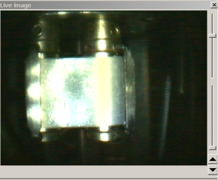
- If the ETC is equipped with an in-built camera, the deformation of the sample can be visually monitored during the test (as shown below) and the images stored with the data file. Sample images are collected at the maximum speed, typically 1-2 seconds per frame. The sampling rate depends on the PC hardware and the camera drivers used.
- When the test is completed, open the ETC while it is at test temperature.
- WARNING: The ETC inside and the drums are hot! Wear protective gloves to clean the SER drums.
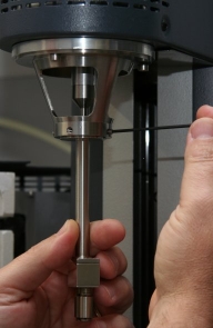
- Pull out the clips with tweezers. Remove the molten polymer with a brass brush. It helps to rotate the drums using the draw rod with one hand while handling the brush with the other hand (see below). When the drums are clean, re-insert the clips.
- Position the drums; lock the bearing; pull out the clips; close the furnace and prepare for the next experiment.
Back to top
Plotting Data
Follow the recommendations below to plot extensional data.
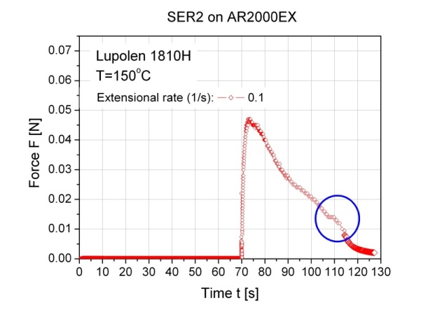
- During the test, plot Elongation Force versus Global Time to monitor the whole experiment. Shown below are the four steps: Pre-stretch, Relaxation and Extension and Final relaxation in one plot. Note, the small disturbance during the extension step, just before the final relaxation starts, is due to the sample making contact with the clip after one full revolution.
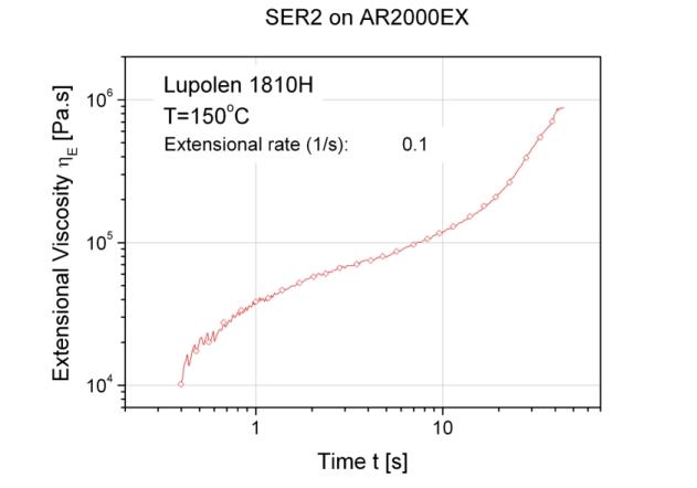
- In order to evaluate the actual extension test, plot the extension viscosity versus time of the third step in a double logarithmic plot as shown below.
- If images have been collected during the test, they can be displayed in the image window when clicking a test point on the result curve.
- NOTE: Images can be saved either from the Point image graph by right-clicking the mouse button in the active window and selecting Save image, or from the File Manager by right-clicking the mouse button highlighting the specific results file and selecting Export all images, or from the Spreadsheet view where individual images can be selected and exported.
Back to top
