| General Information |
| Testing Samples |
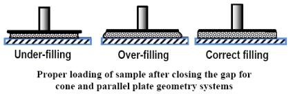
| Sample Loading |
| Cleaning the Geometry |
| Equations |
Parallel Plates are used to test polymer melts, soft solids, and higher viscosity fluids. Disposable plates are used for testing thermosetting resins and materials that cure. The range of geometry sizes, the variable gap, and the ease of loading make parallel plates very versatile geometries that can be used to test materials with a wide range of viscosities. As demonstrated by the equation below for the strain constant, high shear rates can be achieved by using a small gap setting.
![]()
The Parallel Plate geometry is used to test a wide variety of materials including polymer melts, suspensions, and emulsions. Because of the constant gap between the plates, there is a velocity gradient across the plate radius during testing. For the Parallel Plate geometry, the normal force, N, corresponds to the first normal stress difference minus the second normal stress difference, N1-N2.
Options
|
|
Applicable DHR/AR Environmental Systems
|
The recommended gap setting for parallel plates is between 0.5 and 2 millimeters.
After you have finished testing your sample, open the oven (if used), raise the upper geometry and brush or wipe off the sample. You can remove the geometry, if needed. An alternative to cleaning would be to use disposable plates and discard them after usage.
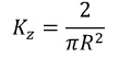
Strain Constant
|
Stress Constant
|
Normal Stress Constant
|
VariablesR = Radius of plates (mm) H = Gap between plates (mm) |
||