| General Information |
| Selecting the Geometry in TRIOS |
| Equations |
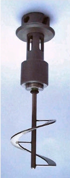
The helical ribbon fixture is a mixing element, when used with the standard 34-mm cup to provide a mixing cell, to test complex fluids. With the helical ribbon fixture, the rheometer can be operated as an instrumented batch reactor to measure the rheological properties under real flow conditions (systemic rheology => the rheology of the system including material and environment), while even conducting complementary measurements such as conductivity measurements.
Since the flow is complex and the material usually behaves in a non-linear fashion, the calculation of a true or representative deformation, or deformation rate, for the mixing element is an issue. Based on a concentric cylinder analogy, average deformation and stress coefficients can be determined, which relate the motor rotation speed to the material deformation rate and the measured torque to the stress.
When selecting the test geometry in TRIOS software, select Special Geometry and enter the geometry constants per the equations below. Also refer to application/product note AAN014 for details on calibration.
Characteristics
|
|
OptionsA narrow high speed mixer or additional sensors (user supplied) can be used in conjunction with the helical ribbon in the ARES-G2, since the ribbon is attached to the stationary transducer while the cup is rotating or oscillating. Note that the calibration constants change slightly with additional elements are immersed in the fluid. Recalibration may be necessary.
|
|
Applicable Environmental Systems
|
The concentric cylinder analogy assumes the helical ribbon mixing device, in a mixing chamber, to be a virtual cylinder in a cylindrical chamber as shown in the figure below. The analogy consists of determining an equivalent inner cylinder with a radius Ri, and the same height as the impeller, which generates the same torque, M, at the same rotational speed, N. The outer cylinder of the rheo-reactor has the same radius as the outer cylinder of the equivalent concentric cylinder system.
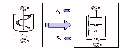
Since the equivalent inner radius varies only slightly with the power law index, n, a calibration procedure can be used for the mixing element using a Newtonian or a well-characterized power law fluid.
Once Ri has been obtained, shear rate and shear stress can be calculated as a function of the radius r.
Ait-Kadi, et al. have shown, that at a given radius r*=( Ri+Re)/x*, where x*=2 for small gaps ( Ri/Re>0.9) the shear rate is essentially independent of the nature of the fluid, i.e., independent of the local power law index. For large gaps x* becomes greater than 2.
When selecting the test geometry in the TRIOS software, select Special Geometry and enter the geometry constants per the equations below. Also refer to TA applications/product note AAN014 for details on the calibration of generic mixing geometries.
The following calibration procedure of the mixing cell is based on the 34 mm cup (PN 402641.901) and the 31.4 mm recessed bob (PN 402674.901). When the helical ribbon is used with a different cup, this cup with an appropriate bob has to be used for the calibration also .The attached spreadsheet provides a template for the calibration using a Newtonian oil. Following the required calibration steps:
Note that the constants below are approximate values for the helical ribbon in the 34 mm standard cup only. A new calibration is required if a mixing cell based on a different cup is used.
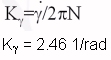
Strain Constant
|
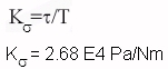
Stress Constant
|
VariablesKs = Stress Constant Kg = Strain Constant N = Rotational Speed T = Torque
|
|