The Interfacial Double Wall Ring
Overview
The Interfacial Double Wall Ring (DWR) measuring system measures the viscous and linear viscoelastic
properties of the interface between liquid-liquid and liquid-air. It consists of a thin, square-edged ring and a
Delrin® trough with a circular channel. The ring and support legs are constructed from a platinum/
iridium (Pt/Ir) alloy, for chemical inertness, ease of cleaning, and wettability. The ring support is made of stainless
steel. It is important that the ring and trough are perfectly aligned (concentricity), and the trough positioned on
the Peltier Plate accurately leveled.
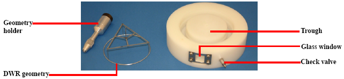
A non-return (check) valve is fitted to the trough below the level of the interface. Together with the supplied
tubing and syringe, this can be used to adjust the lower fluid level, or to add an active ingredient.
- NOTE: Sub-phase contributions, i.e. drag forces applied through the contact surface of the ring with the bulk fluids (lower
and top), are small due to the small contact area of the ring and typically can be neglected (unless interfacial
viscosities below 1x10⁻⁵ Pa.s.m are measured).
Interfacial DWR Specifications
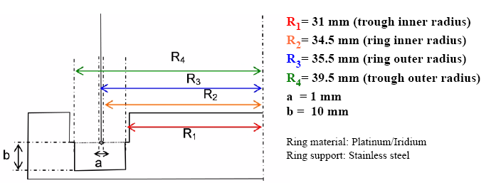
The square cross-section of the ring improves the ability to pin the interface. At the height of the sub-phase fluid
level, a step at the inner and outer channel walls reduces the meniscus area of the fluid; (a) is the diagonal of
the square cross section, (b) is the depth of the channel.
Back to top
Unpacking and Packing the Double Wall Ring
The DWR is extremely delicate and easily damaged. Special care should be taken when removing it from, and returning it to, its packaging.
Unpacking the DWR
- Place the cardboard package on a flat surface with the split line positioned at the bottom.
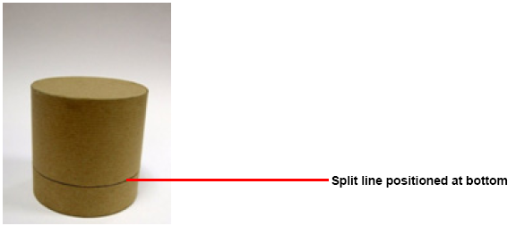
- While holding the package below the split line, gently rotate and lift the top part of the package vertically until it is well clear of the DWR.
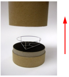
- To remove the ring from the foam, lift from the struts close to the center point. Do not use the ring to lift the DWR.
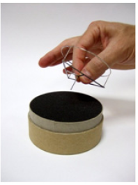
- Once removed from the foam, handle the ring using its main shaft.
Back to top
Packing the DWR
- Lift the ring using the main shaft. Invert and hold using the central struts close to the center point. Do not use the ring.
- Ensure that the inner foam of the top part of the packaging is correctly located, then vertically lower the top part of the package over the lower part of the package.

Back to top
Setting Up the DWR
Follow the instructions in this section to set up the ring.
- CAUTION: Handle the DWR with care: it is delicate and can easily be deformed or
broken.
Zeroing the Gap and Mounting the DWR
Follow these steps to zero the gap and mount the DWR:
- CAUTION: To avoid damaging the DWR, do not zero the gap with the ring.
- Install the Peltier Plate and check the instrument level at the Peltier surface. Ensure that the top and side
surfaces are clean before proceeding.
- Clean the Delrin® trough as described below.
- Carefully install the trough with the window facing forward,
making sure the bottom is fully in contact with the Peltier Plate
surface. Rotate the trough until the spring-loaded locations
balls snap into the Peltier dimples.
- Attach the geometry holder without the DWR to the draw rod.
- Zero the gap by making contact with the jaws of the geometry
holder chuck and the top of the trough (see the figure below).
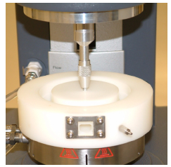
- Set the gap in the geometry form to 12000 micron.
- Raise the instrument head and remove the geometry holder.
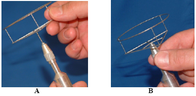
- Loosen the chuck and drop the shaft of the DWR all the way down into the holder, ensuring that the shaft
is fully inserted. Then tighten the chuck. Refer to the figure below.
- Clean the DWR as described in Cleaning the Ring below.
- Reattach the geometry holder and DWR to the instrument and proceed to the next section, Mapping.
Mapping
After the ring is mounted, perform the mapping function as follows:
- Lower the instrument head until the ring is at the measuring position (at the height of the steps in the
trough channel, 12000 microns).
- Use the rotational and oscillatory mapping functions described in the help system. Make sure that you
do not touch the ring after the mapping.
- Raise the ring 20 mm above the trough and load the sample as described in the next section.
Loading the Sample and Locating the Interface
Follow the instructions below:
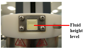
- Load the dense fluid phase (usually water with or without the surface active ingredients) into the trough
until the fluid is at the height of the mark in the glass window, approximately 18.8 mL (as shown below). This corresponds to the height of the steps in the wall of the trough.
- Lower the head until the ring is in the plane of the sample
surface. This may be done by sending the head to the set
gap (12000 micron if the DWR has been zeroed correctly)
or lower the head manually. In any case, fine adjustment
can be made manually.
- If required, gently deposit the light phase (usually the
hydrophobic phase) on top of the dense phase.
- Set up the desired test procedure. There is no difference
between setting up test procedures for interfacial and bulk
rheological experiments.
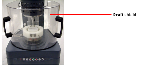
- Fit the draft shield in place, ensuring that the shield does not touch the ring or instrument head while
fitting (as shown below). Then begin your experiment.
Calculation of Interfacial Linear Viscoelastic Properties
The properties of the interface as measured using the TA Instruments DWR measuring system are apparent,
i.e., the contribution from bulk liquid is not subtracted. If the corrected interfacial moduli or viscosity are
required, the drag of the sub-phase needs to be accounted for. This is normally not necessary if water is the
bulk liquid, since the moduli of the water / air interface are very low and sub-phase contributions are only
significant for interfacial viscosities below 10-5 Pa.s.m. only.
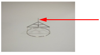
- NOTE: The fabrication process used for the DWR results in more runout than TA Instruments' standard cones and
plates. The total runout of the DWR is inspected using a 3D laser technique and must be better than
0.5 mm in order to pass inspection. This value was determined from the influence on sample measurements taken
during the development process. The human eye can generally perceive a total runout greater than
0.05 mm, so the DWR will always appear to “wobble” when rotating, even when it is within specification.
Back to top
Cleaning
The biggest source of error when making surface rheological measurements is contamination of the ring or dish.
Both the ring and dish should be thoroughly cleaned before and after use.
Cleaning the Ring
To clean the ring:
- Remove the ring from the rheometer.
- Rinse or soak the ring in an appropriate solvent.
- Use a micro-jet gas burner to burn off any additional residue. Position the flame on a small section of the ring. Rotate the ring slowly. Make sure that the entire ring is treated in this way. Do not flame the support of the ring, as it is stainless steel. Do not heat above 800°C to avoid distortion of the ring.
- WARNING: Do not attempt to flame the ring while it is mounted on the rheometer. This could
cause serious damage and may be dangerous. Take care when flaming the ring. It can be held
by the holder, but do not grasp it directly. Ensure that no flammable materials are nearby. Do
not touch the ring or place it in contact with flammable materials until it has cooled down.
Cleaning the Trough
Clean the trough using an appropriate cleaning agent. Then rinse it thoroughly with distilled water if using water
as the subphase.
Replacing the Trough Glass Window
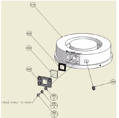
It may become necessary to remove the trough glass window for cleaning or replacement. The diagram below
shows the components of the window assembly. A fresh flexible PTFE gasket (item 020) should be used every
time the components are assembled. To avoid breaking the glass, apply a gentle preload to the metal plate (item
040) with your fingers and tighten the screws evenly in a diagonal pattern starting with a torque of 5cN.m. Tighten
finally to a maximum torque of 10cN.m
Back to top
