| General Information |
| Testing at Other than Ambient Temperature |
| Equations |
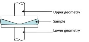
A schematic diagram of the cone and plate measuring system is shown in the figure below. During testing, the cone (the upper geometry) remains stationary while the parallel plate (the lower geometry) moves to deform the sample. The cones have an angle of less than or equal to 4° and are arranged such that they are parallel to the plate during testing.
To avoid contact between the cone and plate, and to prevent damage to either, the tip of the cone is removed. The length of material that is removed from the tip of the cone is referred to as the truncation distance. When testing a sample, the cone is positioned so that the virtual tip of the cone (i.e. if it was not machined away) would be in contact with the plate. At this location, the gap is equal to the truncation distance of the cone. The stress and strain calculations for a cone are geometrically driven and are based on the gap between the cone and plate being exactly the truncation distance of the cone. For this reason, it is critical to test samples with a cone and plate at and only at the truncation distance of the cone. The truncation distances for different cones vary and range from approximately 50 to 100 microns.
The conical angle and truncation distance for each cone are individually determined. These values are included on a calibration certificate that is supplied with each geometry. In addition, these values, as well as the serial number of the geometry, are inscribed on each geometry stem.
The cone and plate geometry is used to test a wide variety of materials including polymer melts, suspensions and emulsions. Because of the geometry of the cone, there is no velocity gradient across the cone diameter during testing. The cone and –plate configuration is the desired configuration for normal stress measurements. For the cone and plate geometry, the normal force, N, corresponds to the first normal stress difference, N1.
Unlike parallel plates, the gap for a cone and plate is fixed, and defined by the truncation distance of the cone. Because of the necessity to operate specifically at the truncation distance, a cone is normally used for isothermal testing only, as temperature changes may lead to changes in gap due to thermal expansion. Invar geometries may be used for tests in which the temperature is varied. Because of Invar's exceptional thermal expansion properties, Invar geometries are used for applications where temperature ramps or sweeps are necessary.
Options
|
|
Applicable Environmental Systems
|
The cone and plate geometry should be used for isothermal testing, as temperature changes may cause thermal expansion of the test fixture. For example, a cone and plate geometry with a 50-micron gap may undergo thermal expansion of 10 microns during testing at various temperatures. This thermal expansion would result in a 20 percent error in the measured gap, and would result in erroneous test data.
Following equilibration, the gap should be zeroed at the working temperature and then set to the testing gap. For applications in which a cone and plate is required and the test temperatures are varied, Invar tools can be used. Invar has a coefficient of thermal expansion that is 10 times less than steel between 0 and 230°C. Outside this range, Invar's thermal expansion properties are similar to steel's. If temperature ramps or sweeps must be performed using the cone and plate geometry, Invar should be used in the temperature range specified above.
Strain Constant
|
Stress Constant
|
Normal Stress Constant
|
VariablesR = Radius of plate β =Cone angle (rad) |
|
|


