| General Information |
| Application |
| Sample Loading |
| Cleaning the Geometry |
| Equations |
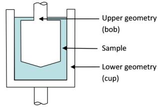
The concentric cylinder geometry is used for testing lower-viscosity fluids that would not stay contained within the parallel plates or a cone and plate arrangement, or would evaporate quickly under standard environmental conditions. A schematic graphical representation is shown below. Due to the large shear surface, the concentric cylinder is also suitable for testing very low-viscosity fluids. The small exposure of the fluids to the atmosphere reduces evaporation effects and makes the concentric cylinder arrangement ideal for testing sensitive solvent- and water-based materials.
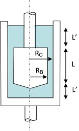
The concentric cylinders geometry allow three types of rotor selections, all based on a common cup. These are DIN concentric cylinders, recessed concentric cylinders, and the vane. The DIN bob has conical bottom with an apex angle of 120° and the ratio of outer and inner cylinder d=1.0847. In order to compensate for the cone contributions, a face factor cL is used in the calculations. The recessed bottom is designed to trap an air bubble underneath the cylinder. The drag of the cylinder face can be neglected and the cL is 0 for a recessed cylinder. The blades of a vane circumscribe surface of a cylinder. As a good approximation, the length and the width represent the length and the radius of an equivalent bob geometry.
The concentric cylinder systems are used for a wide variety of materials including viscous fluids, suspension, emulsions, gels, and also applications. The various cups can be combined with different rotors such as bobs, vanes, and mixing elements.
The DIN bobs are matched with the cups to provide a geometry combination which fulfills the DIN conditions. The criteria for the DIN concentric cylinder systems are:
Note that other non-DIN combinations are possible.
The vane tool is also useful when testing fluids that contain large particles. Many food items fall into this category, including chunky peanut butter, yogurts with fruit, and jams. The vane tool may be used to perform transient experiments (i.e. creep recovery) or low speed steady shear testing. The vane tool is designed to replace the cylindrical bob under certain circumstances. It is used primarily with materials that are highly structured, such as foams and lotions, which may tend to slip with a cylindrical bob. Slippage could mistakenly be interpreted as a yield stress. When using the vane tool with highly structured materials, the material within the vane moves as a solid plug. However, for less shear thinning fluids, there will be secondary flows between the vane rotors. Secondary flows yield incorrect shear data. Therefore, it is important to use the correct tool for the material.
Possible combinations of concentric cylinders and environmental systems for the AR Rheometer are shown in the table below.
Cup Surface
Surface
|
|
Applicable AR Environmental Systems
|
Follow the applicable instructions below for loading a sample.
When selecting the test geometry in the TRIOS software, the vane tool is handled similarly to the standard bob.
Note that the vane typically provides relative material parameters only. In order to compare test results with data obtained using other test geometries, the vane has to be calibrated similar to the mixing elements, such as the helical ribbon (see Application Note AAN014 Non-Standard Geometries for Rheological Characterization.)
To facilitate cleaning of the geometry, the cup has to be removed from the environmental jacket. Unscrew the cup and clean the cup as necessary. Reinstall the cup in the environmental jacket when finished.
Strain Constant
|
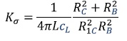
Stress Constant
|
VariablesL = Length of cylinder (m) RB = Radius of cylinder (m) RC = Radius of cup (m) c L= face factor |
|