DHR/AR Rheometer Temperature Systems/Accessory Calibrations
Overview
There are temperature-specific calibrations that are performed from the Temperature systems calibrations document view. To access this view, select Instrument tab > Calibrate > Temperature systems calibrations, or click Calibrate from the File Manager.
Upper Heated Plate (UHP) Zero Heat Flow
The temperature of the UHP is read from a probe positioned within the UHP heater jacket. The temperature of the Peltier plate is read from a probe positioned in thermal contact with the plate, as close to the surface as possible.
- NOTE: Calibration should always be performed on installation of the Upper Heated Plate, and at least annually thereafter. The calibration routine may take several hours, and it is more efficient to perform a single calibration with more points, rather than several calibrations with fewer points.
During the automatic calibration routine, a heat flow sensor determines the temperature gradient between the Peltier plate and the upper geometry. The gradient is reduced to within preset tolerances by adjusting the temperature of the UHP, while the temperature of the Peltier plate is held constant.
After each adjustment, a user-defined stability criterion is applied and, once temperature stability is achieved, comparison is made with the gradient tolerance. When the gradient tolerance condition is satisfied, the temperature value is accepted.
The procedure is repeated for a number of points over a range set by the user. When the calibration routine is complete, the temperature values for the upper geometry determined by the calibration are compared with those reported by the UHP probe to obtain the appropriate offset and span values.
UHP Zero Heat Flow on the AR
Follow the instructions below to zero the UHP heat flow on the AR:
- In the AR Temperature Options screen, ensure that the Cooling temperature and Cooling range boxes contain the appropriate values.
- Click Calibrate. The Calibrate Zero Heat Flow window displays.
- Start temperature: Temperature at which calibration is to begin.
- End temperature: Temperature at which calibration is to end.
- Number of points: Number of temperature points, which will be at equal intervals.
- Initial equilibration time: Time at each set temperature, before readings are taken.
- Adjust equilibration time: Time after each adjustment to the Upper Heated Plate temperature, before readings are taken.
- Average time: Time after each adjustment, over which successive temperature readings are averaged to provide a data point.
- Average stable tolerance: Range within which two successive data points must fall for the temperature to be accepted as stable.
- Gradient zero tolerance: Once stability is achieved, the last data point is compared with the set temperature. If the difference is not more than the gradient zero tolerance, the set temperature is accepted as the temperature value. If the difference is greater than the gradient zero tolerance, a further adjustment is made to the Upper Heated Plate temperature.
- Gradient scale factor: It is suggested that the default value of 1.5 be used, unless other information is available.
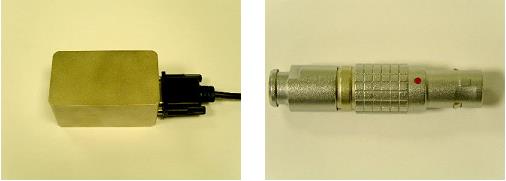
- Connect the calibration box and zero value plug. Follow the instructions given in the window. The Upper Heated Plate calibration box (left image) and zero value plug (right image) are shown below.
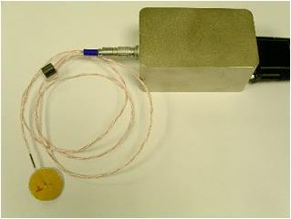
- When the zero value calibration is completed, a window displaying additional instructions displays. Follow the instructions given. The image below shows the zero heat flow sensor connected to the calibration box.
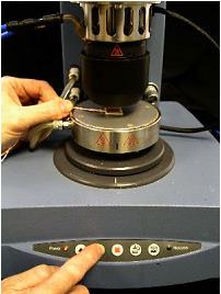
- Use the instrument Head UP and Head DOWN buttons to position the heat flow sensor between the Peltier Plate and the geometry, as shown below (AR Series shown).
- Click Next to begin calibrating. When the calibration is complete, the results display in a new window. The graph shows the temperature difference between the set temperature and the temperature read by the Upper Heated Plate heat spreader probe, plotted against set temperature. The Gradient calibration span is the slope of the best-fit straight line through the data, and the Gradient calibration offset is the intercept. The average and peak errors are also reported. If the average error is less than 0.1°C, and the peak error less than 0.2°C, then consider the calibration acceptable.
- NOTE: Negative slopes are possible.
- To accept the values, click Next. The instrument firmware automatically updates with these values.
- When the calibration is finished, raise the instrument head and remove the calibration sensor. Remove the connector from the electronics box.
- NOTE: For safety reasons, the temperature control is set to idle at the end of the calibration routine, although the final temperature will still be displayed as the set temperature.
Back to top
UHP Zero Heat Flow on the DHR
Follow the instructions below to zero the UHP heat flow on the DHR:
- In the DHR Temperature Options screen, ensure that the Cooling temperature and Cooling range boxes contain the appropriate values.
- Click Calibrate. The Calibrate Zero Heat Flow window displays.
- Start temperature: Temperature at which calibration is to begin.
- End temperature: Temperature at which calibration is to end.
- Number of points: Number of temperature points, which will be at equal intervals.
- Initial equilibration time: Time at each set temperature, before readings are taken.
- Adjust equilibration time: Time after each adjustment to the Upper Heated Plate temperature, before readings are taken.
- Average time: Time after each adjustment, over which successive temperature readings are averaged to provide a data point.
- Average stable tolerance: Range within which two successive data points must fall for the temperature to be accepted as stable.
- Gradient zero tolerance: Once stability is achieved, the last data point is compared with the set temperature. If the difference is not more than the gradient zero tolerance, the set temperature is accepted as the temperature value. If the difference is greater than the gradient zero tolerance, a further adjustment is made to the Upper Heated Plate temperature.
- Gradient scale factor: It is suggested that the default value of 1.5 be used, unless other information is available.
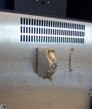
- Follow the instructions given in the window to connect the D-type connector.
- When the zero gap and initial temperature equilibration is completed, a window displaying additional instructions displays. Follow the instructions given. The image below shows the zero heat flow sensor connected to the D-type connector.
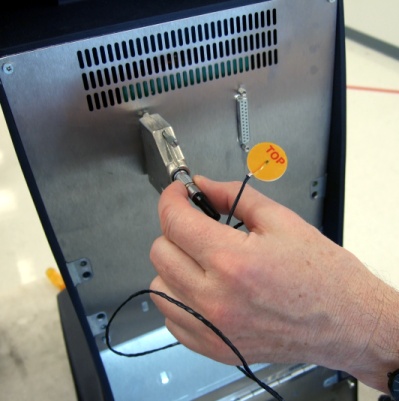
- Use the instrument Head UP and Head DOWN buttons to position the heat flow sensor between the Peltier Plate and the geometry, as shown below (AR Series shown).
- Click Next to begin calibrating. When the calibration is complete, the results display in a new window. The graph shows the temperature difference between the set temperature and the temperature read by the Upper Heated Plate heat spreader probe, plotted against set temperature. The Gradient calibration span is the slope of the best-fit straight line through the data, and the Gradient calibration offset is the intercept. The average and peak errors are also reported. If the average error is less than 0.1°C, and the peak error less than 0.2°C, then consider the calibration acceptable.
- NOTE: Negative slopes are possible.
- To accept the values, click Next. The instrument firmware automatically updates with these values.
- When the calibration is finished, raise the instrument head and remove the calibration sensor. Remove the connector from the electronics box.
- NOTE: For safety reasons, the temperature control is set to idle at the end of the calibration routine, although the final temperature will still be displayed as the set temperature.
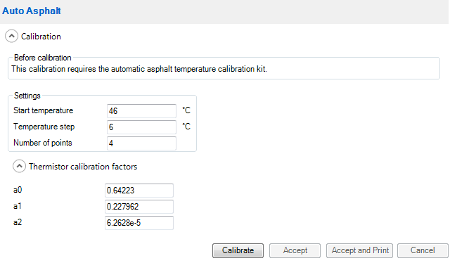
Automated Asphalt
The Automated Asphalt Temperature Calibration Kit contains an Ohm meter (with the required accuracy) for use with the NIST-traceable Cannon DSR Temperature Probe. The calibration controls the rheometer temperature and reads the probe resistance from the meter via a USB interface (a driver can be downloaded from http://www.cooldrives.com/wividrforprc.html). Once the temperature probe is positioned between the sample plates, the calibration process is entirely automatic.
The calibration wizard allows entry of the certified probe coefficients and uses these to calculate the temperature from the meter reading. The reading is monitored over the 5 minute equilibration time specified in the standard method, resetting the timer if the value varies by more than 0.1°. The average value over a further 1 minute period is then recorded before moving to the next temperature. The data is displayed graphically during the calibration; once complete, the calibration can be stored to the instrument and/or printed. The data is also stored as an XML file.
- NOTE: If the Agilent Ohm meter does not have a driver for Windows Vista or Windows 7 use the driver for prolific chip USB Serial Adapters available for download at this link: http://www.cooldrives.com/wividrforprc.html.
Back to top
UV Irradiance
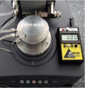
To obtain absolute irradiance of the UV light, the light source must be calibrated. For the UV light accessories, a portable radiometer/dosimeter is provided to measure the irradiance at the upper plate. This is the irradiance seen by the sample during the curing reaction. The irradiance is a nearly linear function of the power supplied to the LED or OmniCure™ 2000. For the blue light LED accessory, a test sheet is provided that gives the irradiance at 100% power. This can be used in the absence of a suitable radiometer.
- Select UV Irradiance. The dialog shown below displays. Follow the steps described in this section to calibrate. Fit the radiometer sensor as shown below and click Calibrate.
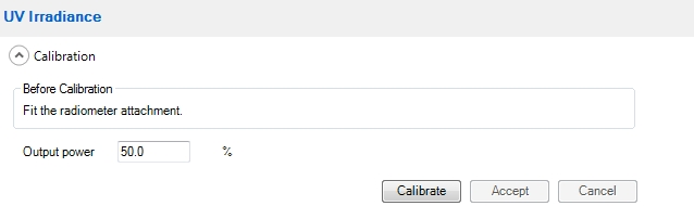
- NOTE: The output power% field is automatically filled in with a value that is appropriate for the accessory and radiometer. Using other values will not damage the accessory, but may result in the radiometer going over range.
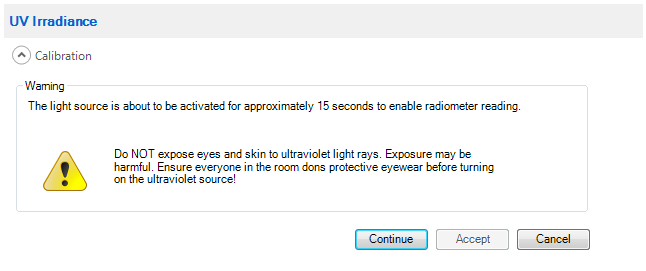
- After clicking Calibrate in step 1 above, the screen below appears. Click Continue.
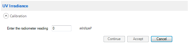
- When prompted, enter the radiometer reading in the field shown below.
Back to top
