| Introduction |
| Using the AR Gap Control Panel |
The Motor controls provide the ability to view real-time motor parameters, as well as control operations related to this component.
To access the Motor section of the Control panel, click the Experiment tab > Controls ![]() and select Motor. For more information on the Control panel, refer to Understanding the Control Panel.
and select Motor. For more information on the Control panel, refer to Understanding the Control Panel.
The table below explains the Motor controls (from left to right on the Motor toolbar).
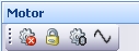 (AR Series Motor panel)
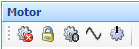 (DHR Series Motor panel)
| Item | Function |
|
Stop motor |
Sends a value of zero torque to the motor, effectively turning it off but still enabling it to free-rotate. |
|
Lock |
Lock sends a value of zero velocity to the motor, effectively locking it in place (useful for sample trimming). Unlock sends a value of zero torque. The motor is always unlocked at the start of an experiment. |
|
Zero displacement |
Sets the displacement to zero. |
| Start Manual Oscillation | See Using Manual Oscillation below. |
| Go to Default Position (DHR Series only) | Drives the motor shaft to the default position. |
| Move to alignment position (DHR Series only) | Drives the motor shaft to a home position set during the axial mapping calibration. |
|
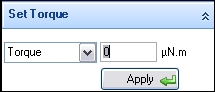
Set Torque
|
Enter a value and click Apply (green arrow). The value can be torque or stress. |
|
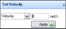
Set Velocity
|
Enter a value and click Apply (green arrow). The value can be (angular) velocity or shear rate. |
|
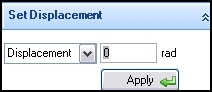
Set Displacement
|
Enter a value and click Apply (green arrow). The value can be (angular) displacement, strain, or %strain. |
|
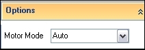
Options
|
Auto – Default condition suitable in most cases. Stiff\Medium\Soft – Allows you to match the stiffness of the motor control loop with the stiffness of the sample. |
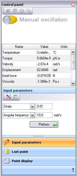
Manual oscillation is a special instance of the Control panel that is activated by selecting the ![]() icon on the Motor control. It is useful for dynamically probing the sample prior to setting up a full experiment.
icon on the Motor control. It is useful for dynamically probing the sample prior to setting up a full experiment.
Upon selecting Start Manual Oscillation, the status section displays Manual oscillation (shown below). There is no change to the section that displays the real-time variables. The functional section allows entry of the control parameters, the numerical data for the last point, and the point view (waveform) for the last point. The variables displayed for the last point can be selected from a right-click pop-up menu.
The two icons ![]() are End manual oscillation (left icon), and Options (right icon). These measurement options mirror those in the oscillatory procedure steps.
are End manual oscillation (left icon), and Options (right icon). These measurement options mirror those in the oscillatory procedure steps.