Configurations

| General Information |
| Installation and Loading Samples |
| Possible Tribo-Rheometry Geometry Configurations |
| Equations |
The tribo-rheometry geometries can be used to quantify the Coefficient of Friction (CoF) between two substrates with or without a lubricant. The tribo-rheometry setup can be configured with the following 4 geometries:
DHR: ETC and Peltier Plate
Follow these instructions to install the geometry. Refer to the section Possible Tribo-Rheometry Geometry Configurations for geometry component identification and assembly.
See also
Fitting a Geometry on the DHR
The sample loading procedure depends on the Tribology fixture to be installed. For the Ring on Plate and Three Balls on Plate geometries, the substrate is usually attached to the bottom plate or cup using an adhesive.For most applications, a double sided pressure sensitive adhesive can be used. For the Ball on Three Plates, the 3 plates are the substrate. This fixture is designed to work with stiff substrates. The substrate has to be cut into rectangular samples (16x6 mm2) that are 1–2 mm thick. The Ball on Three Balls geometry is used to study the lubrication of materials. Note that the stainless steel balls can be exchanged with spheres of other materials if desired.
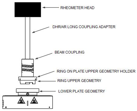
The tribo-rheometry geometries are set up by combining specific parts of the tribology testing kit. In this section, the assemblies of the four basic tribo-rheometry geometries are shown for :
a DHR configured with the Peltier plate and Environmental Test Chamber (ETC).
Note that some parts are instrument specific; other components that are specific to the test geometry are the same for all instruments.
In order to make sure that the load (axial force) is distributed evenly on the contact surface, a flexible coupling is used on the upper test fixture. Two couplings are provided, a soft Aluminum and a stiff Stainless Steel coupling.
The maximum permissible axial load for the soft coupling is 20 N.
Do not use the stiff coupling for axial loads below 6 N.
The Ring on Plate test fixture geometry consists of a 32 mm ring and a plate with the substrate attached. The ring can be mounted into the holder in two ways; either as a full ring or as a half ring (the ring is interrupted in 3 sections such that only half of the ring is in contact with the substrate). For testing with lubricants, the lower plate can be replaced with a cup.
The ring's dimensions (OD = 32 mm, ID = 29 mm) allows for a well-defined contact surface permitting the computation of the friction and normal stress. Because of the large contact surface, uniform contact with the substrate along the circumference can be a problem for stiff substrates– the ring is, therefore, best suited for softer substrates. For lubrication testing, it is advantageous to use the half ring for better lubrication of the contact surface.
| DHR ETC Configuration | DHR Peltier Configuration |
|
|
|
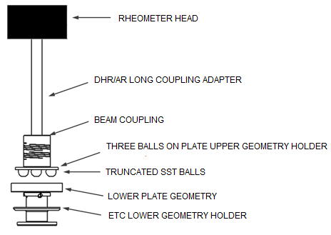
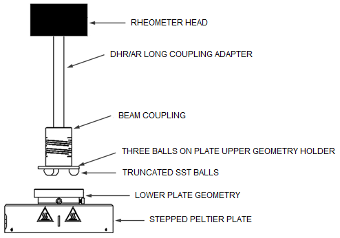
The Three Balls on Plate geometry consists of 3 spheres arranged on a circle of 15 mm radius and a lower plate with the substrate attached. For testing with lubricants, the lower plate can be replaced with a cup.
The spheres have a diameter of 5/16” (7.9375 mm) and provide a point contact with the substrate. The Three Balls on Plate geometry is therefore well suited for hard and stiff substrates. Because of the point contact between the substrates, the contact surface depends on the moduli of the substrate and the spheres; as a result the stresses are difficult to compute. Therefore only friction force and load are calculated for this geometry. However, you can manually edit the stress and normal stress geometry constants (File Manger > Geometries > Edit selected geometry) to calculate friction stress and normal stress if desired.
| DHR ETC Configuration | DHR Peltier Configuration |
|
|
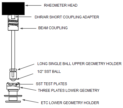
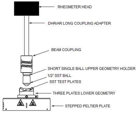
The Ball on Three Plates test geometry consists of a sphere on top of three plates on the bottom that are arranged in a circle and oriented at 45°. The lower plates are the test substrate and are held using a supporting frame.
The sphere has a diameter of 1/2” (1.27 mm) and the three plates are 16x6 mm2in size. The sphere provides a point contact with the 3 substrate plates. The Ball on Three Plates geometry is designed for hard and stiff substrates. Because of the point contact, the contact surface depends on the moduli of the plates and the sphere; as a result, the stresses are difficult to compute. Therefore only friction force and load are calculated for this geometry. However, you can manually edit the stress and normal stress geometry constants (File Manger >Geometries > Edit selected geometry) to calculate friction stress and normal stress if desired. The Ball on Three Plates geometry requires only a small amount of substrate and lubricant.
| DHR ETC Configuration | DHR Peltier Configuration |
|
|
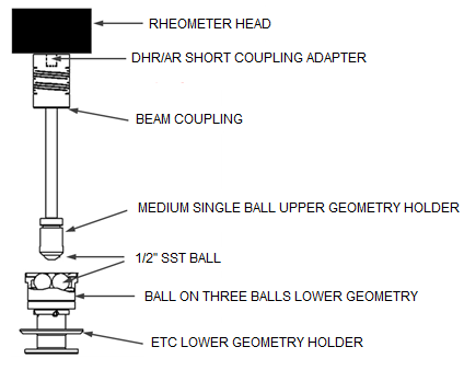
The Ball on Three Balls test geometry consists of a ball as the upper substrate and three balls arranged in a circle as the lower substrate. The 3 lower spheres are held in place using a supporting frame. An important application of this geometry is for testing the lubricity of asphalt.
The spheres have a diameter of 1/2” (1.27 mm). The upper ball provides a point contact with the 3 lower balls. Ball on Three Balls tribo-rheometry geometry is designed for lubrication testing. Because of the point contact between the substrates, the contact surface depends on the modulus of the spheres; as a result, the stresses are difficult to compute. Therefore only friction force and load are calculated for this geometry. However,you can manually edit the stress and normal stress geometry constants (File Manger > Geometries > Edit selected geometry) to calculate friction stress and normal stress if desired.
| DHR ETC Configuration | DHR Peltier Configuration |
|

|
Ring on Plate |
||||||||||||||
|
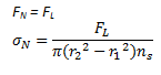
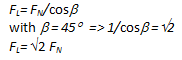
Actual Load FL:
|
||||||
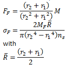
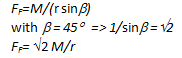
Friction Force FF:
|
||||||
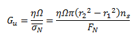
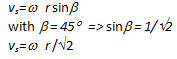
Sliding Speed vs:
|
||||||
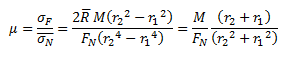
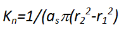
Friction Coefficient µ:
|
||||||
DimensionsSphere radius: r=0.00635m arm d: 0.015 |
||||||
|
||||||
VariablesFN = normal force [N] M = torque {N.m] FL = actual load [N] FF = friction force [N] d = arm [m] Strain rate = sliding speed [m/s] Strain = sliding distance [m] |
Actual Load FL:
|
||||||
Friction Force FF:
|
||||||
Sliding Speed vs:
|
||||||
Friction Coefficient µ:
|
||||||
DimensionsSphere radius: r=0.00635m arm d: 0.00449 b=45° |
||||||
|
||||||
VariablesFN = normal force [N] M = torque {N.m] FL = actual load [N] b=Angle [rad] FF = friction force [N] d = arm [m] r=sphere radius p [m] Strain rate = sliding speed [m/s] Strain = sliding distance [m] |
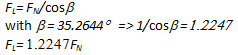
Actual Load FL:
|
||||||
Friction Force FF:
|
||||||
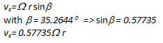
Sliding Speed vs:
|
||||||
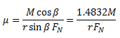
Friction Coefficient µ:
|
||||||
DimensionsSphere radius: r=0.00635m arm d: 0.007398 b=35.2644° |
||||||
|
||||||
VariablesFN = normal force [N] M = torque {N.m] FL = actual load [N] b=Angle [rad] FF = friction force [N] d = arm [m] r=sphere radius p [m] Strain rate = sliding speed [m/s] Strain = sliding distance [m] |